Videos from the Recitation
This week is about PCB production. I had already designed a board last week based on Anthony's video, but decided to start small and test the basic functions. It's really more about using the Bantam milling machine and getting all the settings right, and later soldering, of course.
Process
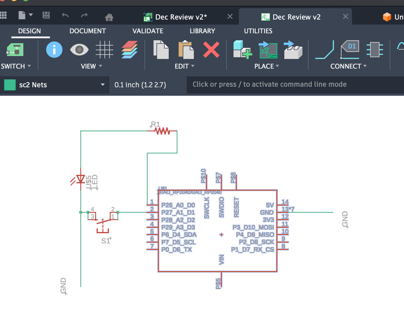
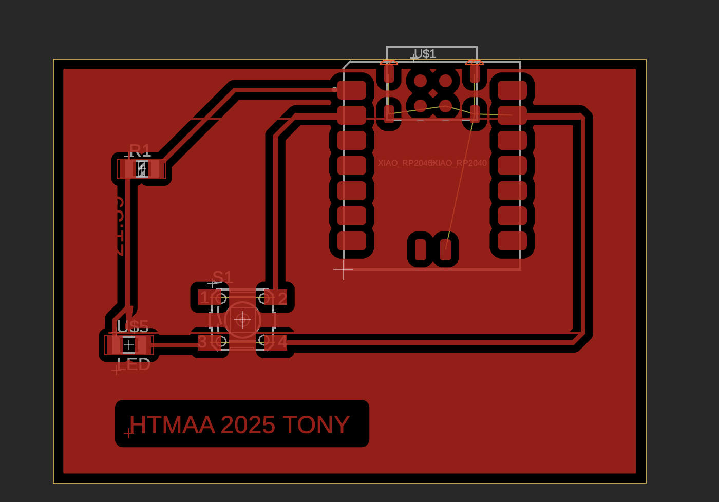
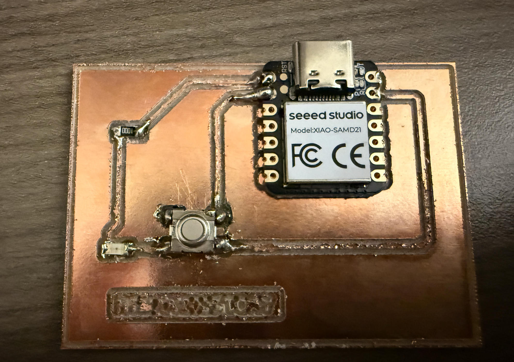
First, I removed some of the parts from the already very simple board in Anthony's last week's video. I kept only a switch, an LED, a resistor, and a microcontroller on the board.
Export
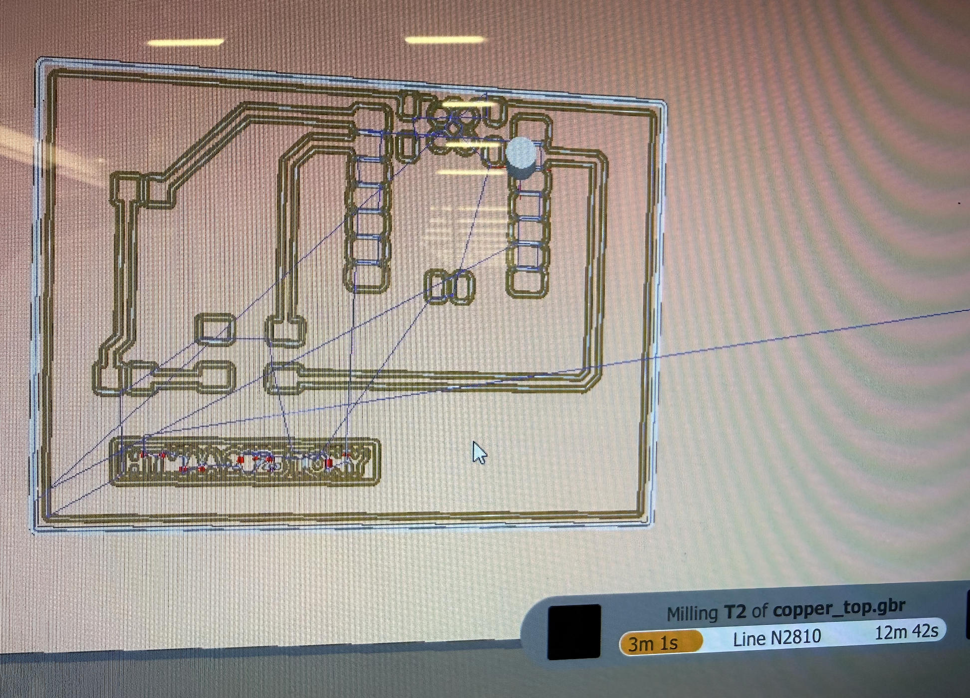
Switch to the Manufacturing tab, select CAM Processor, and export. This generates three folders: Gerber, Drill, and Assembly. Gerber is the one needed for milling.
| Folder | What it contains | Main purpose | Needed for Bantam milling? |
|---|---|---|---|
Gerber |
2D PCB layers such as top copper, bottom copper, and board outline (e.g. copper_top.gbr, profile.gbr) |
Defines where copper stays or is removed; used by PCB fabs and CAM tools to manufacture the board | Yes — use top copper and outline files |
Drill |
NC drill files describing hole positions and sizes (vias, through-holes, mounting holes) | Tells fabrication tools where to drill holes in the PCB | No for SMD-only Bantam milling (no holes to drill) |
Assembly |
Component placement diagrams, pick-and-place data, and BOM-related files | Used by assembly houses to place components automatically on the finished PCB | No — not used for DIY milling |
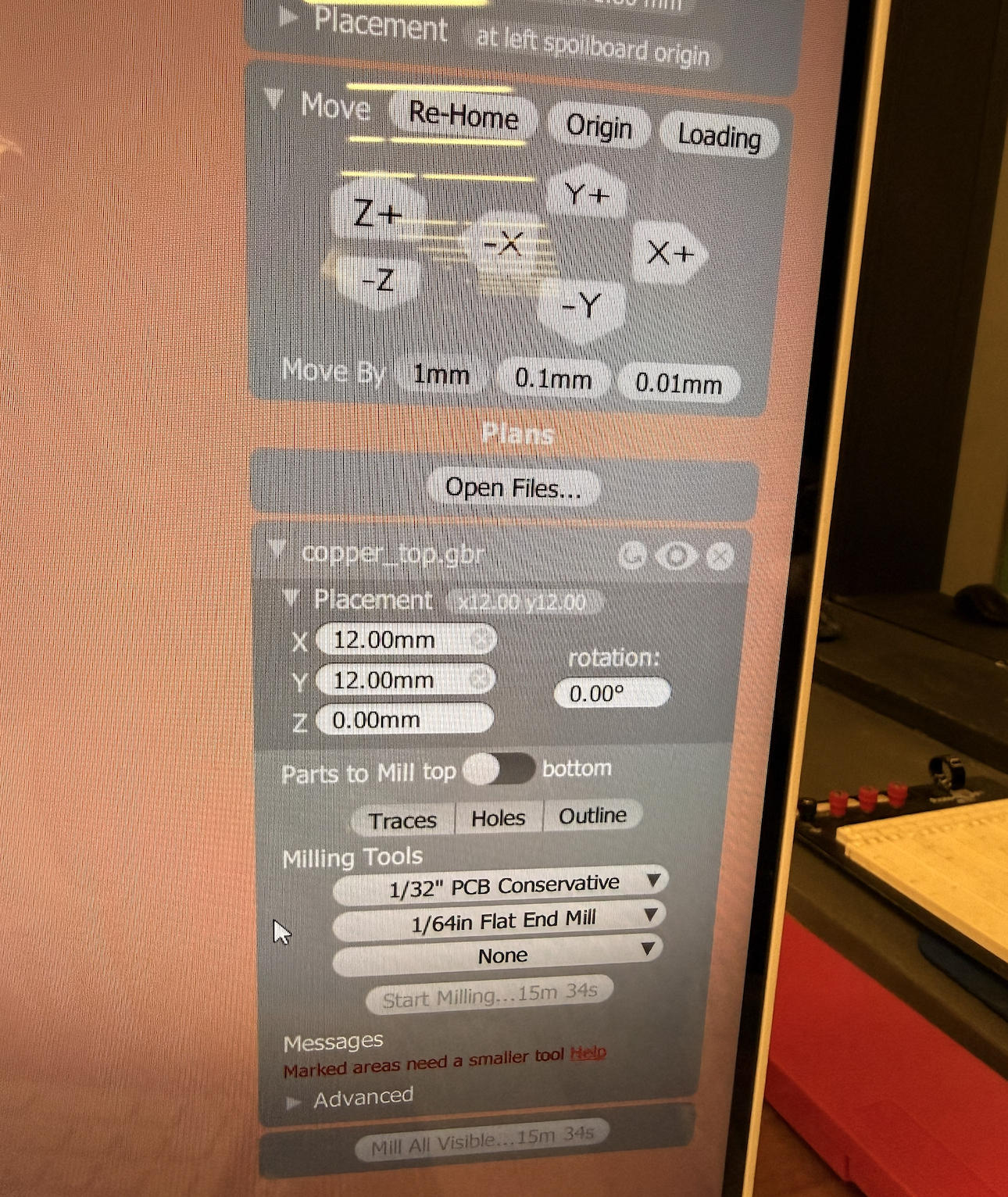
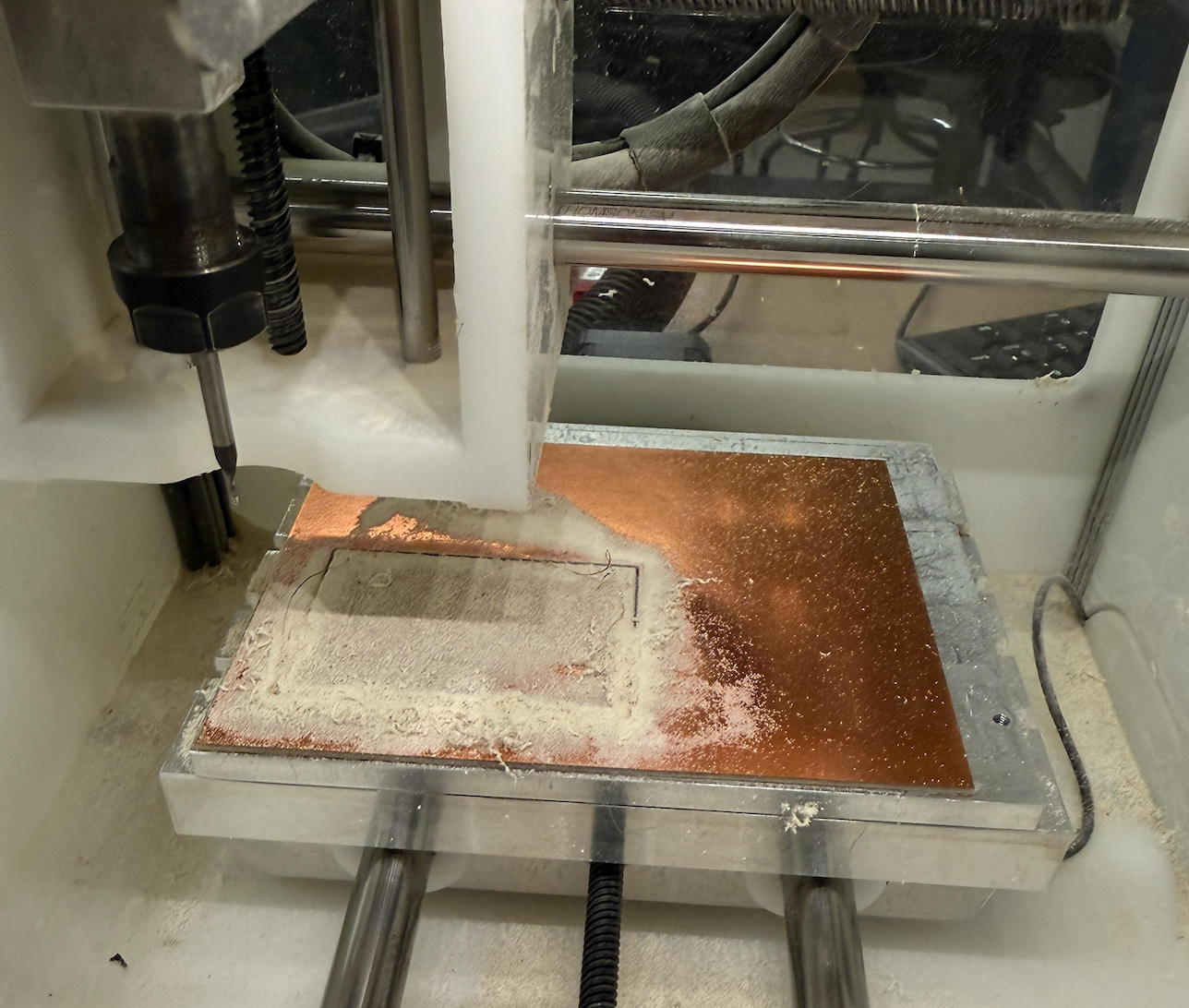
Milling
Why Need Both Drill Bits?
Because each tool is designed for a different task:
| Tool | Purpose | Why Needed |
|---|---|---|
| 1/64" Flat End Mill | Isolation routing for traces | Fine detail, copper removal |
| 1/32" PCB Cutter | Cut-out / profile | Strength and deeper cutting |
Trying to cut the outline with a 1/64" will break the tool.
Trying to mill traces with a 1/32" will ruin the circuit.
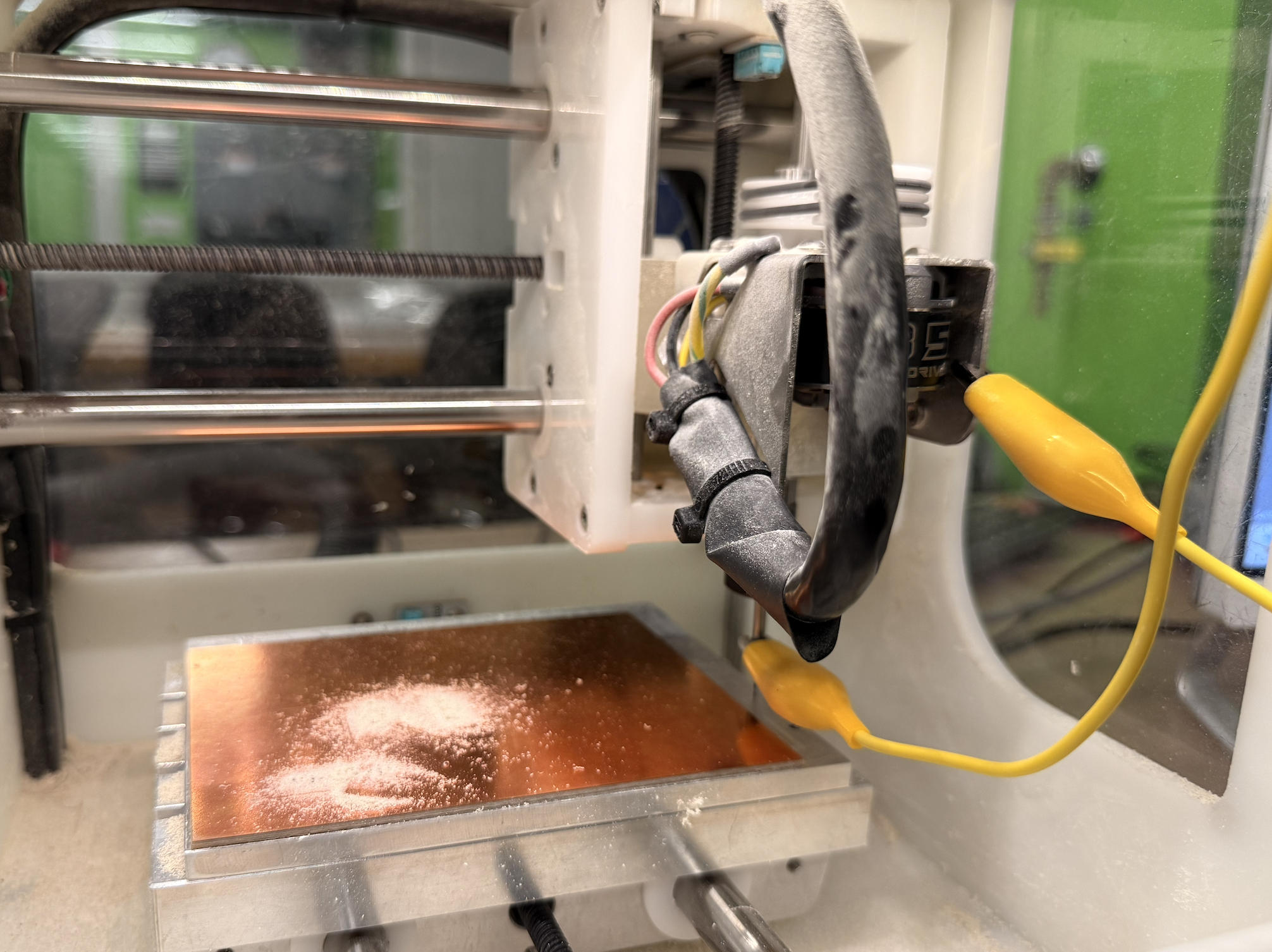
Purpose of the Probing/Grounding Cable
The cable that connects the drill bit to the machine frame is a probing/grounding cable. It lets the milling machine detect the exact moment the metal tool touches the PCB surface by completing a small electrical circuit.
- The PCB is electrically connected to the machine frame (ground).
- The drill bit is connected through the probe cable.
- When the bit touches the PCB, the circuit closes and the machine knows the precise Z=0 height.
Without this cable, the machine can't accurately find the PCB surface, which can lead to cutting too shallow (copper not removed) or too deep (broken tools and damaged boards).
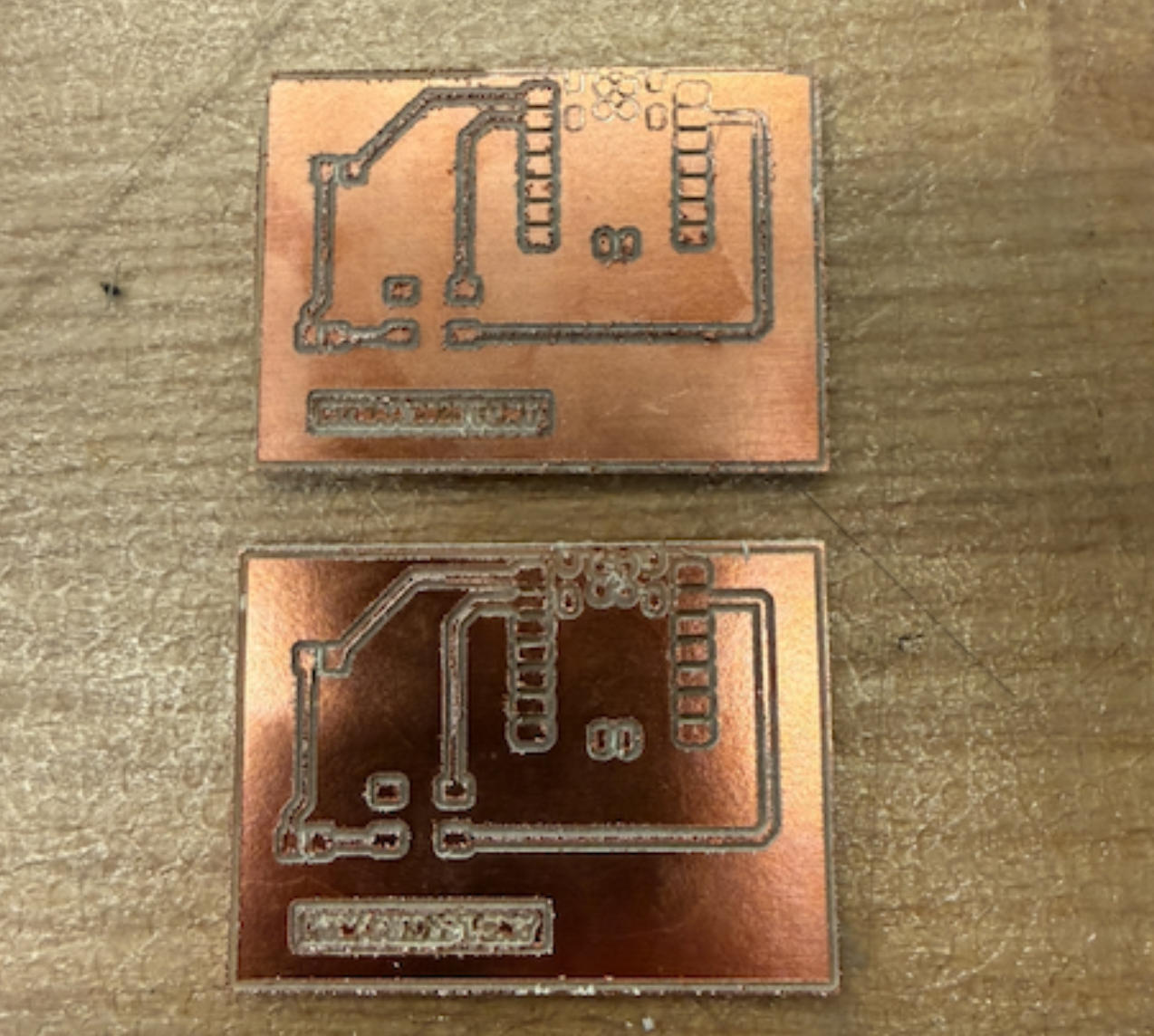
Milling Results
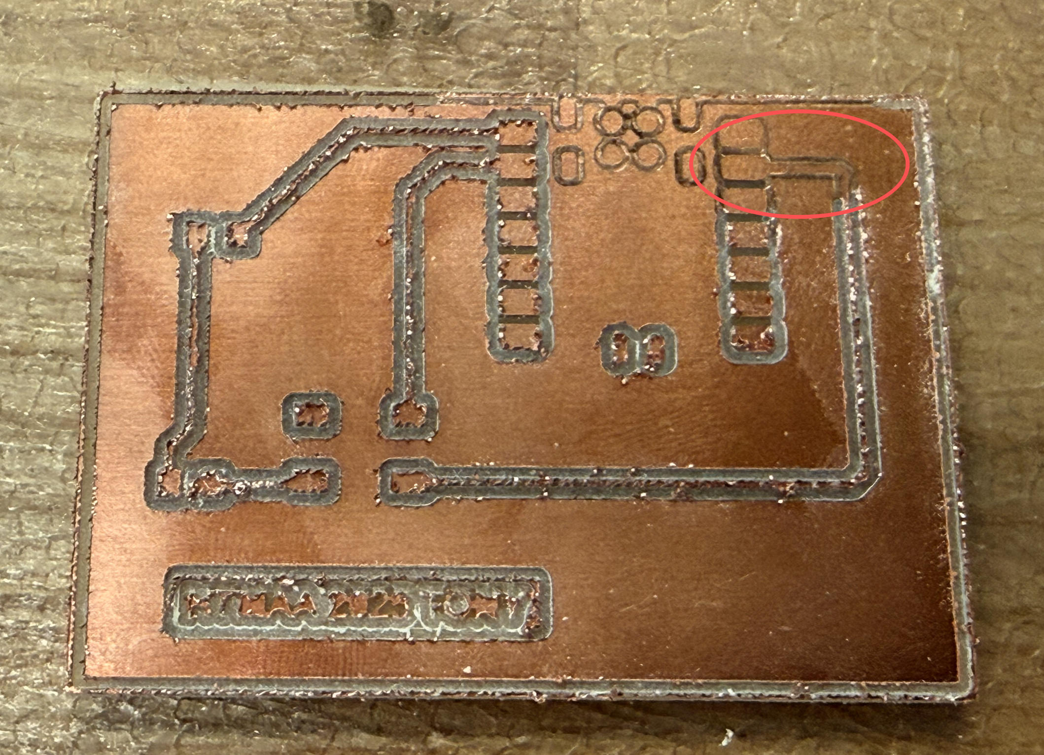

Troubleshooting
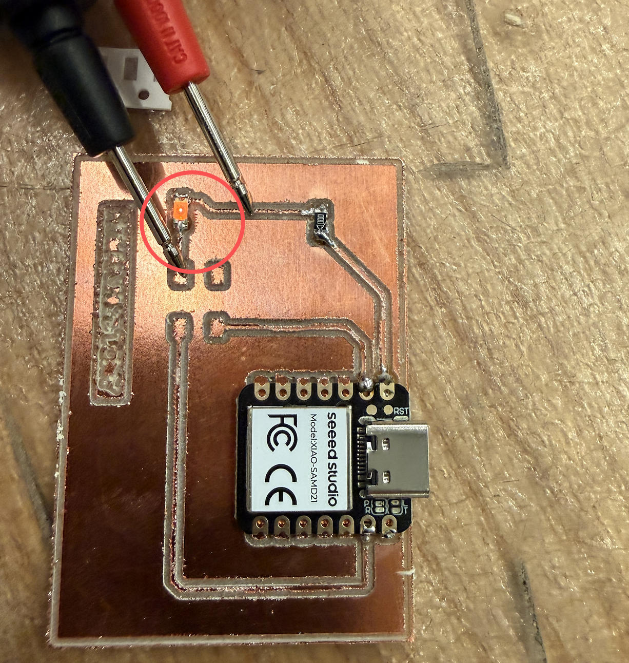
Then things started becoming really frustrating. The LED would not light up. I think part of the confusion came from an earlier test: when I tried to detect a short, the LED briefly lit up, which made me believe that the traces were already connected and that the switch was only meant to physically close the loop.
I used a multimeter to look for possible shorts or breaks, but the board appeared fine. I kept troubleshooting until the lab closed at midnight.
Side note: I had ordered Chipotle and completely forgot to pick it up. Apparently, if you don't show up before the store closes, they don't leave the order on a shelf for later pickup — they just throw it away.
A few days later I ran into Anthony and wanted him to help me troubleshoot. He said I needed to write code to make the whole thing work.
This was beyond stupid. I swear I've seen this scene on TV before: a guy takes apart an entire machine trying to figure out why it won't start, only to realize in the end that there's a switch he never flipped — or that the machine wasn't even plugged in.
Arduino Programming
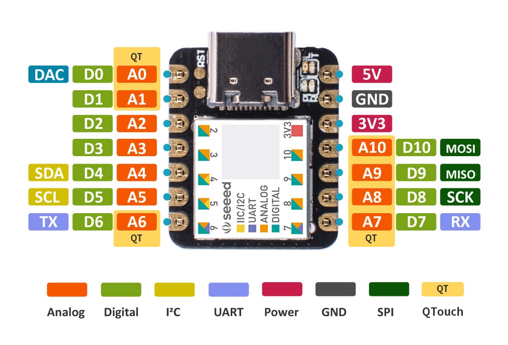
Fortunately, the XIAO — SAMD21 is really well documented. Everything I need to program this board, including the setup in Arduino IDE, can be found here.
Also, even though this is the most basic board, I do get to control all there is to control about this LED. That includes timing, interval, and frequency. What is a blinking light?
Morse Code Messages
Yes, Morse code. Let's send a few messages.

Arduino Code
// SAMD21: LED on pin 0, optional button on pin 1
const int LED_PIN    = 0;
const int BUTTON_PIN = 1;

// Morse timing (in milliseconds)
const unsigned int DOT_DURATION         = 200;             // length of a dot
const unsigned int DASH_DURATION        = DOT_DURATION * 3;
const unsigned int SYMBOL_SPACE         = DOT_DURATION;
const unsigned int LETTER_SPACE         = DOT_DURATION * 3;
const unsigned int WORD_SPACE           = DOT_DURATION * 7;

bool ledState = false;

void setup() {
  pinMode(LED_PIN, OUTPUT);
  digitalWrite(LED_PIN, LOW);

  pinMode(BUTTON_PIN, INPUT_PULLUP);

  Serial.begin(9600);
  while (!Serial) {
    ;
  }

  Serial.println(
    "SAMD21 ready. Waiting for commands: ON, OFF, SOS, STAY, HTMAA"
  );
}

// Blink a single Morse symbol ('.' or '-')
void blinkSymbol(char symbol) {
  if (symbol == '.') {
    digitalWrite(LED_PIN, HIGH);
    delay(DOT_DURATION);
  } else if (symbol == '-') {
    digitalWrite(LED_PIN, HIGH);
    delay(DASH_DURATION);
  }

  digitalWrite(LED_PIN, LOW);
  delay(SYMBOL_SPACE);
}

// Play a raw Morse pattern string
void playMorsePattern(const char* pattern) {
  for (int i = 0; pattern[i] != '\0'; i++) {
    char c = pattern[i];

    if (c == '.' || c == '-') {
      blinkSymbol(c);
    } else if (c == ' ') {
      delay(LETTER_SPACE);
    }
  }
}

void handleCommand(String cmd) {
  cmd.trim();
  cmd.toUpperCase();

  if (cmd == "ON") {
    ledState = true;
    digitalWrite(LED_PIN, HIGH);
  } else if (cmd == "OFF") {
    ledState = false;
    digitalWrite(LED_PIN, LOW);
  }
}

void loop() {
  if (Serial.available()) {
    String cmd = Serial.readStringUntil('\n');
    handleCommand(cmd);
  }
}
File Downloads
The following files have been checked and verified with ChatGPT:
- LED Function Check: download Check.ino
- SOS Message Code: download SOS.ino
- HTMAA 2025 Message Code: download HTMAA2025.ino
- STAY Message Code: download STAY.ino